III. Normal Operation:
- Before test, the kind of scale has to be determined upon the specimen. The following operation takes scale C as an example without specific notice, i.e. to test with diamond cone indenter and total test force up to 150kgf. It can be referred to for other scales.
1. Preparation prior to normal operation
- First of all, spend some time on studying the functions of every parts of the indication dial gauge, where there are hardness readings, division lines, longer pointer, shorter pointer, etc. (see Fig-14)
- Black division lines are for hardness indication. The black digits at outer ring are for hardness indication of scales A and C while red digits at inner ring are for scale B. Different scales can be composed of by changing the indenter and the weights (for detail, please refer to Table 2).
- The shorter pointer indicates the load of preliminary test force.
- The longer pointer indicates the hardness value of tested specimen.
- The letters B and C are the symbols of scales. The position of Letter C is the zero point of division value of scale C or A. The position of Letter B is that of division value 30 for scale B.

Fig-14 Schematic diagram of Indication dial gauge
1) Regulate the loading ratio of main test force
a. Make sure that the unloading handle (20) is at the position of unloading. Otherwise, turn it to unloading position slowly (2 to 3 seconds or so) as per the unloading direction shown on the unloading label (see Fig-15).

Fig-15 Loading and unloading handles
b. Turn the load changeover handle (24) to the position of 150kgf and make sure that the Number 150 on the handle aligns with the red mark, as shown in Fig-16.

Fig-16 Test force selection
c. Place the standard hardness block 40~50HRC onto the worktable
d. Turn the hand wheel (4) so that the hardness block raises the indenter until the shorter pointer points to red mark, and then the preliminary test force has been applied.
e. As per the loading direction on loading label, pull the loading handle (2) slowly towards the front of the machine body (approximately 4 seconds) to the limit position, and then the main test force has been applied (see Fig-15).
f. Keep eyes on the longer pointer of indication dial gauge and make sure that it takes 4 to 8 seconds for it to start turning till stop. Otherwise, regulate it by turning oil needle as follows: First, loosen the bolt cap on the buffer (see Fig-17), turn the oil needle lightly. To turn it anticlockwise, the loading speed will rise, while to turn it clockwise, he loading will slow down. Repeat the above steps until everything is ok, and then tighten the bolt cap.

Fig-17 Regulating the oil needle
2) Test force selection
Turn the load changeover handle until the number of selected test force points to the red mark (see Fig-16).
Note: When changing the test force, the unloading handle must be at the unloading position (see Fig-15, i.e. at the limit position on the right hand). Otherwise it will cause damage to the hardness tester #RT90-0330.
3) Install indenter (see Fig-18)
The tester #RT90-0330 is equipped with a steel ball indenter when exiting works. Following steps should be followed when reinstalling.
a. Put on the indenter and tighten it slightly to the extent that it will not fall down.
b. Place the standard block onto the worktable.
c. Turn the hand wheel to apply preliminary test force.
d. Pull the loading handle leftwards to apply main test force on the indenter (see Fig-15).
e. Tighten the screw. That’s all for the installation.

Fig-18 Install the indenter
4) The specimen should meet the following requirements
a. It should have certain size and thickness. The distance between two centers of adjacent indentions and that between the center of indention and edge of specimen should be more than 3mm. The minimum thickness should be no less than 8 times to the depth of indention. After test, the binding surface of the specimen should be free of obvious hint of deformation. The minimum thickness is subject to the quality of material and the load selected. The table 4 is only a reference.
b. The surface to be tested should be flat generally. If it is a curved face and the radius of curvature is not too big, the test result should be corrected. The correction of cylindrical specimen is included in Table 5 and Table 6.
c. The surface of specimen should be polished with the finish no less than
 . The polishing should not influence the hardness, i.e., no hardening or tempering phenomena. The surface finish of binding face should be no less than
  . The surface to be tested, binding surface and worktable surface should be kept clean. The specimen shall be placed on the worktable reliably and no movement should happen.
d. Be sure that the test force applied should be perpendicular to the surface to be tested. To test the specimens with curved shapes or other abnormal shapes, specialized anvil should be adopted and proper position should be selected. For example, V-shaped anvil shall be used for cylindrical specimen. To test the specimens hollow inside, much attention should be paid not to produce deformation by test force, or the measured hardness value is incorrect.
Table 4 Minimum Thickness of Specimen
|
Scale |
Hardnessvalue (HR) |
Minimumthickness (mm) |
Scale |
Hardness value
(HR) |
Minimum thickness
(mm) |
|
A |
70 | 0.7 |
B |
80 | 1.0 |
| 80 | 0.5 | 90 | 0.8 | ||
| 90 | 0.4 | 100 | 0.7 | ||
|
B |
25 | 2.0 |
C |
20 | 1.5 |
| 30 | 1.9 | 30 | 1.3 | ||
| 40 | 1.7 | 40 | 1.2 | ||
| 50 | 1.5 | 50 | 1.0 | ||
| 60 | 1.3 | 60 | 0.8 | ||
| 70 | 1.2 | 70 | 0.7 |
2. Testing procedures
1) Clean the top end of elevating screw rod and both sides of worktable, place the worktable into the insertion hole of elevating screw rod. Proper worktable should be chosen according to the size of the parts to be tested.
2) Clean the binding surface of specimen and place it onto the worktable. Turn the hand wheel to lift up the worktable slowly to push up the indenter. No stop or reverse action is allowed from the start until the shorter pointer points to the red mark and the longer pointer point right upwards after three circles of clockwise turning. The allowance is ±5 division lines. If it is more than 5 division lines, the spot should be invalid and repeat the test by choosing other spot.
3) Turn the outer shell of indication dial gauge until the longer pointer aligns with the long division line between Letter C and Letter B (see Fig-19, either anticlockwise or clockwise turn is all right).

Fig-19
4) As per the loading direction on the loading label, pull the loading handle (2) towards the front of machine body slowly (around 4 seconds) up to the left-handed limit position (see Fig-15), then the main test force has been applied and the longer pointer will rotate (see Fig-20).

Fig-20
5) After the longer pointer stops rotating obviously, remove the main test force by pushing slowly (2 to 3 seconds) the unloading handle clockwise to the right-handed limit (see Fig-15). Get the readings from corresponding scales on the indication dial gauge. For diamond indenter, read from the black digits at the outer ring. As for steel ball indenter, read from the red digits at the inner ring. The hardness value for this example shall be 45 HRC (see Fig-21). Turn the hand wheel to let the specimen down until the surface being tested is separated from the indenter. Move the specimen and carry on new test by repeating the above steps from 2) to 5). Please be advised that the binding bottom surface of specimen shall not be away from the worktable.

Fig-21
6) The protective sleeve of elevating screw rod is designed to prevent dust from the elevating screw rod. It shall be kept outside the elevating screw rod when the tester is not in use or the height of specimen is smaller than 100mm. When the height is over 100mm, it must be removed; otherwise the worktable will be propped up, resulting in invalid test.
CAUTIONS:
 During the step 4 and step 5, the load changeover handle should not be turned so as to prevent damaging the tester.
 After any item among indenter, specimen and worktable is replaced, the first test should be regarded invalid.
IV. Maintenance
1. Cleaning and Lubrication
- Cover the tester #RT90-0330 with dust-proof guard when it is not in use for a long time.
- Fill adequate amount of machine oil into the contact face between elevating screw rod and hand wheel periodically.
2. Oil filling to the buffer
If the pointer of indication dial gauge rotates rapidly at the beginning and then slowly later on when applying main test force, it means that the buffer is lack of machine oil. Lift up the oil carpet over the buffer and fill with clean machine oil No. 32. At the same time, pull and push the loading and unloading handles several times to let the piston move up and down so that the air inside the buffer is completely get rid of, until there is oil overflowing from the top when the piston falls down to the bottom (see Fig-22).

Fig-22 Oil filling
3. Calibration
- Inspect the accuracy with the standard hardness block supplied with the tester #RT90-0330.
- The tester should be calibrated regularly, usually the period can not be more than 12 months.
- Clean the worktable and standard hardness block and carry out the test on the working face of the block. It is not allowed to make a test on the binding bottom surface.
- If the reading error is too much, besides the conventional inspection listed in Table 7, check whether the binding surface of standard hardness block is burry. If yes, please polish it with edge stone.
- When carrying on the test on different spots on standard block, the test block should be pulled along the worktable rather than removed away from the worktable.
V. Hardness Value Correction
Since the measured value for convex specimen is lowered, the correction should be added. To the opposite, as for the concave specimen, correction should be deducted.
Table 5 Corrections to scale C and A for cylindrical specimen
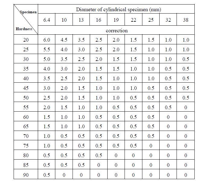
Table 6 Corrections to scale B for cylindrical specimen

VI. Troubleshooting
When the tester breaks down, the following contents can help you predict the troubles and recommend the trouble shooting methods. If the problems remain unsolved, please contact with our after-sale service department rather than dismantle the tester by yourself.
|
Phenomena |
Reasons |
Remedies |
| Elevating screw rod is held back |
Rusted or chips |
Get rid of the chips on elevating screw rod and hand wheel, fill with lubricants |
|
Main test force can not be applied |
Oil needle of buffer locked |
Adjust oil needle to eliminate locking (refer to P. 16) |
|
Weights not hanged properly |
Adjust the position of weights as per operation manual (refer to P. 10) |
|
|
Larger pointer trembles when applying main load |
The levelness of worktable not right |
Adjust the levelness (refer to P. 13) |
|
Hardness value not precise |
Test force |
Check whether selected test force conforms to the requirements of the scale |
|
Distance of indention |
Check whether the distance between the centers of two adjacent indentions is too near | |
|
Indenter |
Check whether the indenter conforms to the requirements of the scale |
|
| Check whether the clearance between the indenter and main shaft is removed | ||
|
Replace the indenter if damaged |
||
|
Worktable |
Check whether there are impurities between worktable and elevating screw rod | |
|
Check whether selected worktable is suitable for this specimen |
||
| Check whether protective sleeve props up worktable | ||
|
Specimen |
Check whether the surface tested is perpendicular to the direction of test force |
|
|
Check whether the rear surface is burry |
||
|
Check whether the specimen is too thin |
||
|
Environment |
Check whether there is mechanical vibration resources around |
|
|
Check whether the temperature is kept at 10℃ to 30℃ |
||
|
Others |
Calibrate the hardness tester by standard block supplied |
